Introduction
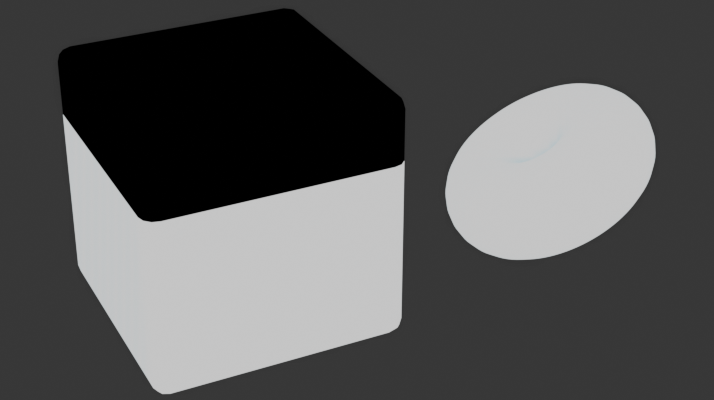
The canvas of 3D design does not lend itself well to organic shapes, in contrast to hard surface modeling, where digital accuracy works in tandem with the need for precision. Organic modeling acts as the antithesis to the core inner-workings of computer assisted modeling. They require a high level of generated randomness, or that same randomness generated by a complex, real world simulation of the natural world, often limited by the hardware or application. And I believe there is no better example of the struggle between the analogue and digital canvas than 3D water.
Rendering water is one of the fundamental challenges 3D artists face. With so many ways to implement water in 3D engines, from simulations to shaders, and strict constraints around performance, representing it in 3D is hard, not to mention shaders with transparency effects in general. Several games have taken on the challenge of creating realistic water, with some instances better than others, and many instances using several different kinds of techniques. For example, water in 3D can use combination of both fragment and geometric shaders, like Sea of Thieves and AC: Black Flag, while other implementations can use only fragment shaders, like Super Mario: Sunshine. And while both have their strengths and weaknesses, what if you wanted to try and create your own version yourself?
How you implement water will jurastically change depending on the application; movies, video games, architecture design mockups, all use different interpretations of water. So while one implementation may be extremely powerful for it’s respective usecase, it usually won’t be the same in others. Which is to say, as a preface, that there are many different ways to create water, and some ways that don’t include shader programming at all. But, given my experience with shaders, I wanted to try to challenge myself to take on this sure-to-be timeless issue of water in 3D.
Table of contents
Open Table of contents
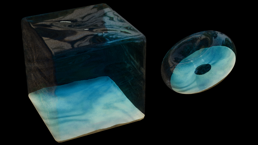
Shader 1: The outer-water shader
The start of any wave based shader is to use a Wave Texture. Lets use a Sin wave and give it some distortion:
Then, If we take that and plug it into a bump node, adjust the distance to our liking, and then also adjust the color, roughness, alpha, and transmission of the BSDF like so…
Its output should get really close to what we’re looking for.
Bump Maps broken?
If your bump maps aren't working, it's probably because it needs a normal map input. You can plug the Normal output of a Texture Coordinate node into a Bump node's normal input to fix this.
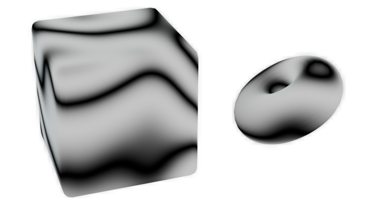
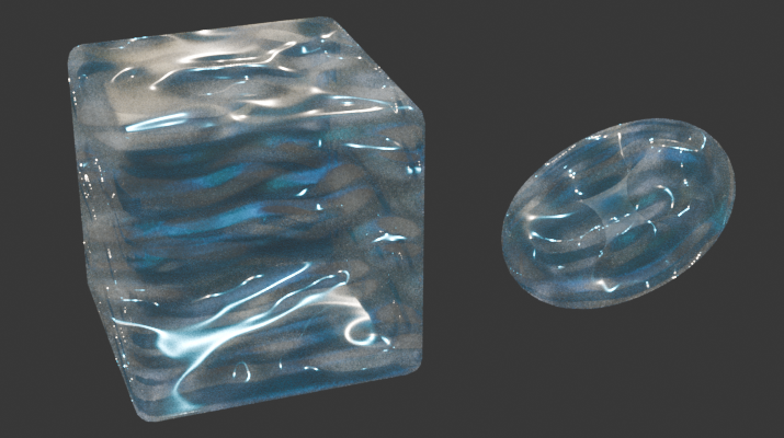
But it’s still missing something. At this point it really just looks like a floating piece of saran wrap. The first thing we can do is reduce the roughness (to either zero or near zero, like 0.025) or add more waves to our wave texture and multiply them together to make it look more complex. This will also help make it look better when we actually implement the waving effect, through animation. You can also increase the bump normal distance as well, to amplify the wave effect. Here’s what the new node layout will basically look like.

Keep in mind that I’ve also offset the scale of each wave texture slightly, with a ratio of 1:3:6, so that they aren’t all the same. The output will look something like this:
But it’s still not finished…
The fog…
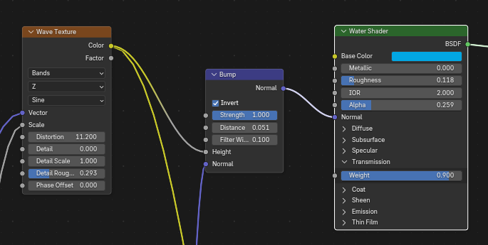
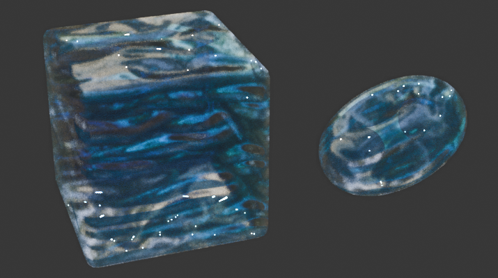
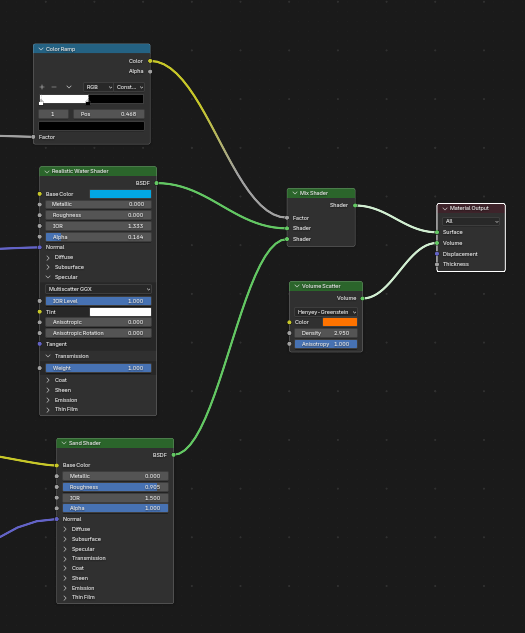
Next, lets add some fog to the object to really sell the idea that it isn’t just a single mesh with a shader on it. To do this, search for the “Volume Scatter” node and plug its output into the “Volume” input of the Material Output. If you get really into things, you can go look at Blender’s documentation on the specific Volume Scatter phases, as some of them have been made specifically for the purpose of simulating water’s ‘fog-like’ effect, but I’m just going to keep it on the Henyey-Greenstein phase. Now you’re going to have to adjust every component of the Volume Scatter node, but there’s only 3 variables, so it won’t be that hard.
| Input Field | Description |
|---|---|
| Phase Dropdown | How the light passes through the fog. |
| Color | The color of the fog. This will change depending on the anisotropy. |
| Density | This is the density of the fog. Keep in mind that setting the color of the fog to something dark will just make it less dense, which you should be doing with this variable instead. |
| Anisotropy | This controls the relative amount of backward and forward scattering. I have no idea what that means. |
How you should adjust the Volume Scatter node:
- Phase Dropdown:
Fournier-Forandis built for light in underwater environments, but it only works in cycles.Henyey-Greensteinis most useful for skin tissue, but it will still work for our underwater use case and is the only option with support for Eevee as well. - Color: Set this to the opposite of whatever your water’s color is, with a little offset, too, if you’re feeling saucy. It won’t make sense at first, but if you adjust the anisotropy properly, it’ll look correct.
- Density: I usually set this between 4-15, depending on the lighting conditions and the size of my mesh.
- Anisotropy: For some reason, setting this value to either positive or negative 1 creates an ocean-fog effect. I personally think a value of
1looks best, but its up to you. Adjusting this value will also influence the color of the fog, which is why we set the actual fog color to the opposite of the water, in compensation.
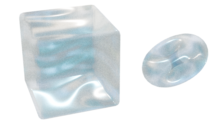
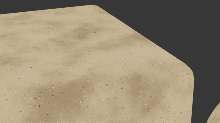
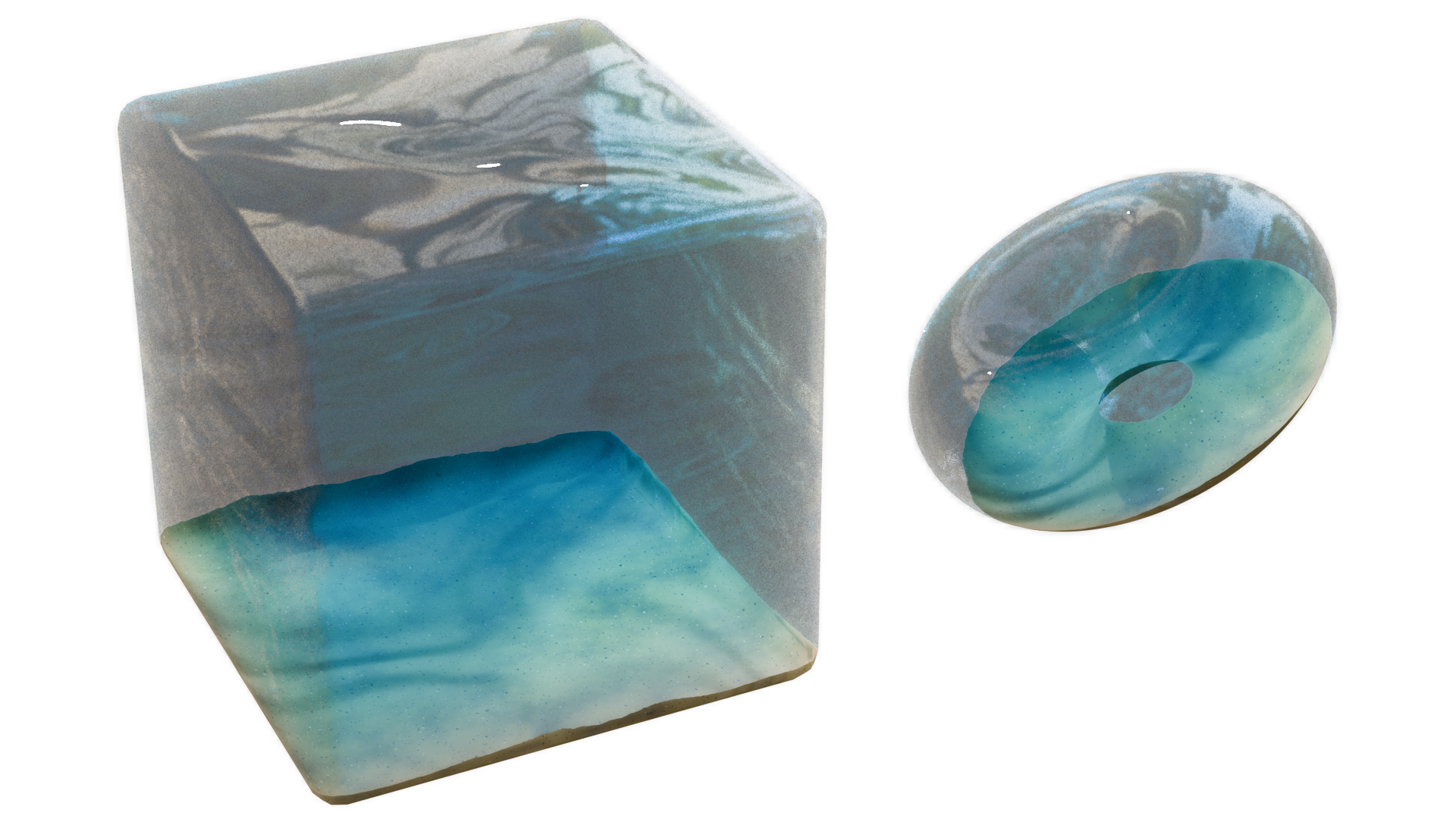
Shader 2: Sand
I’ve always been enamored by those diorama scene’s I’ve seen other (far more talented) blender artists create, and I figured I should implement a sand shader at the bottom to get one step closer to that. This will also help contextualize our water so that it isn’t randomly floating in space.
I should also mention that because I’m using the Eevee renderer for this, things like water caustics are going to be a bit more difficult to implement, but I personally don’t see that difficulty as a challenge, more so “artistic freedom”… since we’ll basically have to fake it ourselves.
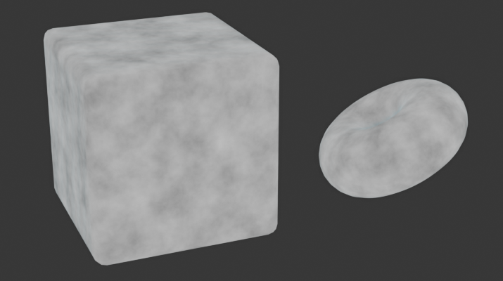
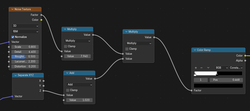
Like almost every shader, lets start with a noise texture
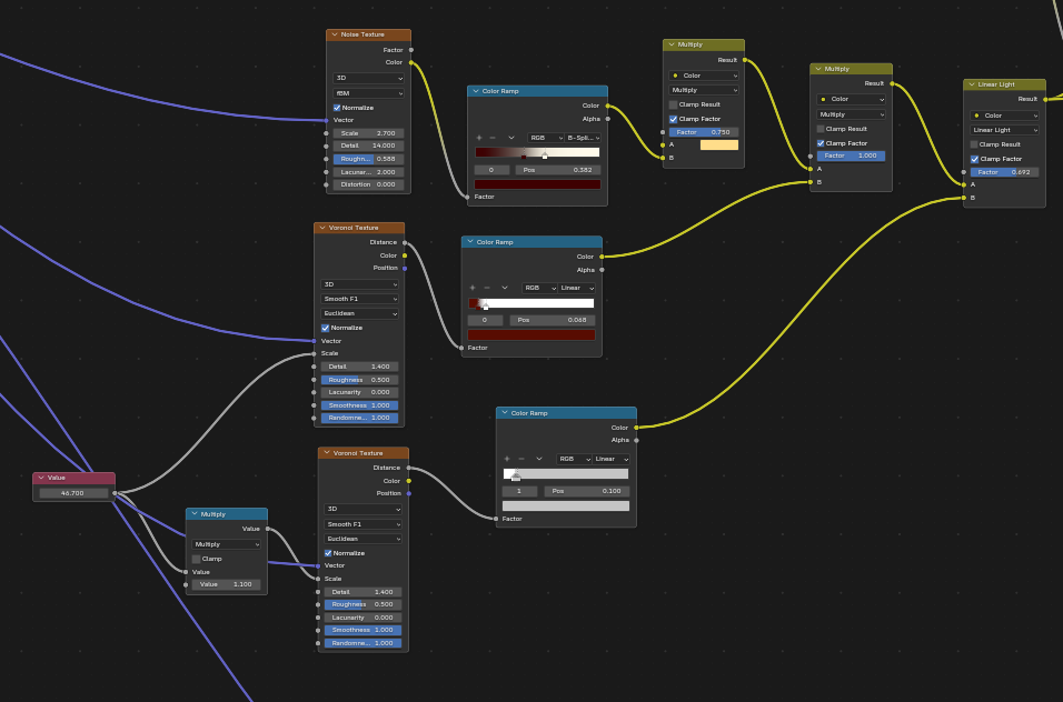
Now nothing about this really screams “sand”, so let’s color ramp it to make it pompompurin-colored. Then also add two Voronoi textures, set to Smooth F1 in the feature output dropdown, scaled at slightly different intervals—much like our waves. Feed those into their own color ramps, and adjust the color ramps accordingly so you have a series of very small, sand grain-like dots. Now multiply and add those respectively to the original colored noise texture, one dark and one light, and you’ll successfully have the albedo for your sand texture.
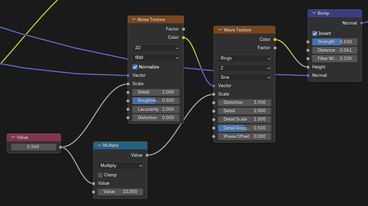
Once we’ve got our shader’s albedo down, lets create a normal map for the waviness of the sand itself. One of the coolest things you can do with shader nodes is use a Noise Texture as the “mapping” of an object, and luckily for us, this is one of those usecases that is perfect for its application. Use a wave texture set to Rings on the Z axis. Give it some distortion, and finally, grab a Noise Texture to feed into the vector input on the Wave Texture. Getting the scale relationship between the two textures right can be finnicky, so I’m using a ratio of 1:20 for the scale of the Noise Texture to the Wave Texture. Now, plug the Wave Texture's Factor into the Height input of a Bump node. I suggest inverting it if your mesh’s normals are outward-facing, since we’ll be seeing the sand from the inside of the mesh in the water. Finally, plug that Bump node into your BSDF’s normal input.
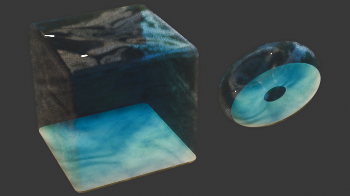
With the Albedo and Normal complete, we can view the shader. It looks OK, but I really like the water caustic effect that water can have, and I want to implement something like that into it. Doing this won’t require many extra nodes, as we’ve basically computed the waves for said caustics. Let’s just take the wave that would’ve been applied to the portion of the shape where the sand is, and apply it as a layer effect (mix, multiply, darken, add, etc.) so that it gives the right shadow/lighting.
To start, grab the output of the base “waves” node from the water shader and put it into two Color Ramps. Plug the Color Ramps into the Factor of their own Mix Color nodes, and set one node to “Darken” and the other to “Soft Light”. Next, invert one of your color ramps (just move the white color to the left side and the black to the right) such that they both effect the opposite ranges of each other. Now you can set the Darken node’s B color to a dark grey and the Soft Light node’s B color to a lightish grey. You can adjust these colors to your liking, as they basically determine how strong you want the caustics effect to be. Now plug the output of our sand’s albedo into these node’s A color input, chaining the two together. You might also need to adjust the Color Ramps of the caustics effect to make sure they don’t overlap too much.
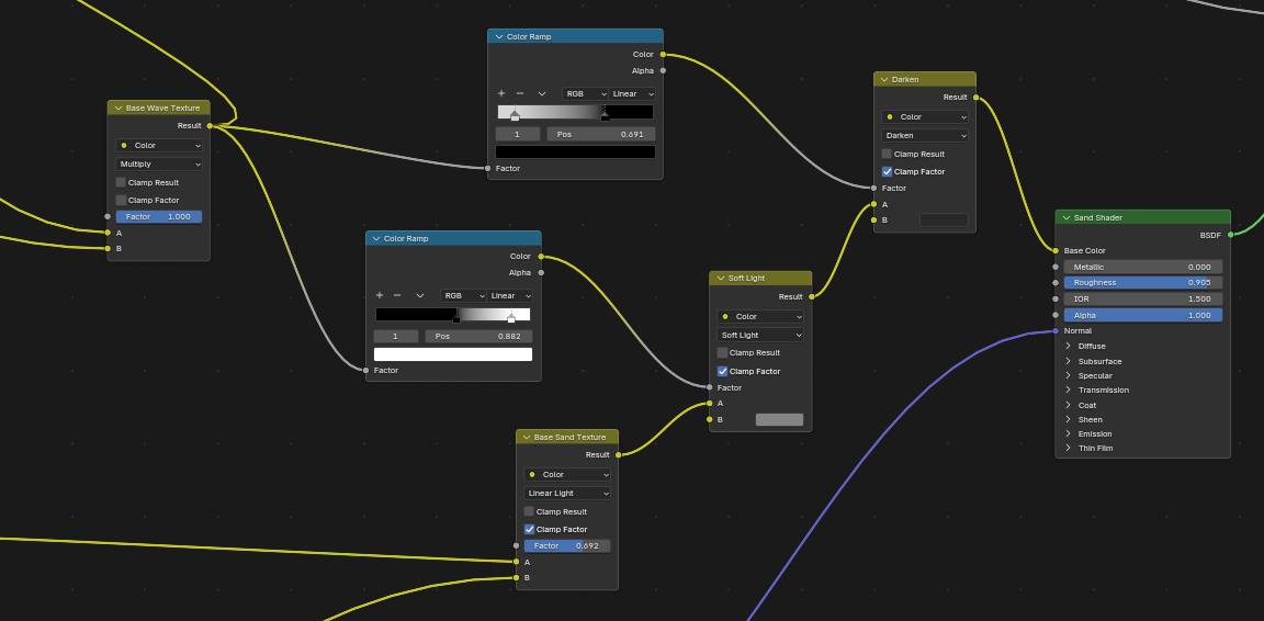
If you like, you can also adjust the transmission and specularity of the texture to be the max value, as that is how water actually behaves. And with that, we’ve created a caustics effect on the sand, as well as the normal bumps, but we still haven’t created the transition between the two shaders.
The transition
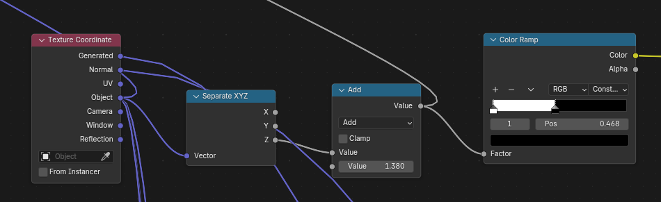
To make it such that the bottom of the object contains only the sand, we first will grab a Texture Coodinate node. This node will allow us to get the information about the object’s vertex coodinates, which we can use to get a location reference for where the shader transition should take place. At this point, you will want to plug in the Object output of the Texture Coodinate node into a Mapping node. The Mapping node allows us to offset and scale of the vectors that we feed into it. With the Mapping node, we can do things like scale the water along a single axis to make it biased in a direction, and we can also add a Driver or a set of keyframes to the Z value of the texture’s location, so that the waves will actually “scroll” or move over time. For the textures that won’t be scrolling, and don’t need individual axis scaling, I’d suggest plugging in the Object output of the Texture Coordinate directly into the Vector input of all other textures, as this will allow for a consistent application of our shader. If you need to control the scale of a texture, add a Value node and plug that into the Scale input of the texture itself.
Alright, with that out of the way, lets create our transition. Take the Object output of the Texture Coordinate and feed it into a Seperate XYZ node. This allows us to grab just the Z axis, or the axis that will get the height of the object. Throw that into a Color Ramp node, and set the Interpolation dropdown of the node to Constant, that way the instant one shader ends, the next one begins. If you view the output of the Color Ramp at this point, it probably either shows the texture being all white or all black, this just means that the object’s local position’s are too low or too high. You might also see your object being split into two equal black and white parts, which if the bottom part is supposed to be the sand, its likely too high up on the object. To adjust for these issues, add a Math - Subtract node (or and Math Add node) inbetween the Seperate XYZ and the Color Ramp. If you adjust the value of the subraction, you’ll be able to manipulate where the transition point will be.
Our transition so far will look like this:
If you think about what the data of this texture looks like, all of the black areas have a value of zero, and all of the white areas have a value of one. That seperation is going to allow us to tell Blender “if the texture has a value of 0 (is black) then use the Water Shader, and if it has a value of 1 (is white) use the Sand Shader.
This is where the Mix Shader comes into play. Any node with a Factor input is basically looking for this same sort of transition from black to white. If we plug our two shaders into the A and B slots of the Mix Shader node, and then the output of our transition Color Ramp into the factor, we should see the two shaders appear on our object, seperated in accorance with where the black part stops and where the white part begins.
The output of our Mix Shader node should look like this:
I’m warping it.
If you look at our render so far, you can see that the shaders themselves look pretty good, but, especially if you move the transition between the two to be in the center of the object, it becomes pretty obvious how artificially the sand “sits” on the bottom of the object. To fix this we can warp the transition to make it higher in some parts and lower in others.
This is pretty simple, but it can be hard to wrap your head around. We basically take our transition point and multiply it by a Noise Texture. Just like the scale between the different sizes of waves, there is a delicate balance between the influence of the noise texture and the prominence/location of the transition point, so it can take some toying with before you get the settings right.
So: Add a noise texture, plug it into a Math - Multiply node, and plug the output of the Math - Add/Subtract node we used earlier to control the height. Chances are you’ll end up having to adjust the value you used for the Math - Add/Subtract node earlier, but thats fine. Plug the output of the Multiply node into the color ramp we made, and everything should be setup for it to work. Now you just have to adjust the values of the transition math to make it work. You may also have to add another Multiply node right after the noise texture to make it more prominent, if it isn’t showing up enough. You can copy the values I used if you just want to get it working right away. The tough part is that the multiply nodes affect not only the prominence of the Noise Texture but also the height of the transition. You might have to adjust the color ramp as well.
You can also view the output of the Color Ramp directly, like we did before, to see what it looks like before we apply the shaders.
And thats the shader!
The animation:
If you set up the Mapping Node mentioned earlier correctly, you should be able to control the movement of the wave textures by adjusting the node’s Z value. Now you can move it manually yourself to get it working, but that doesn’t actually work if you want to render, say, an animation, although it can be nice adjusting it yourself to get just the right look for the waves. So how do we actually animate it?
There are two ways. The first way is to use Key Frames. All you have to do is move the playhead of the animation panel to the first frame, go back into the shader, right click on the X value, and click Insert Keyframe. Then go to the end of the timeline and adjust the Z value of the mapping node to something different, maybe add 10m to it, then right click it and insert another keyframe. If you play back the animation, you should see the texture scrolling. The drawback to animating it with keyframes is that the duration of the keyframes limited to the range you’ve applied them, but if you wanted it to go on forever, you’d have to keep moving them to adjust. The other issue with animating it by hand is that the speed of the scrolling is proportional to the time between the keyframes and the distance you make the texture scroll. If you wanna increase the speed, you have to adjust both of these properties.
The second way is to use drivers. Instead of inserting a keyframe, just click on the Z input field of the mapping node and type #Frame/100. This will set the value of the Z offset to the number of current frames, divided by 100. With drivers, the animation will continue on forever and you get complete control over the speed of the movement. If you want to change the speed, just adjust 100 to be something bigger or smaller, in accordance with making it slower or faster, respectively.